1. Problème de référence#
1.1. Géométrie#
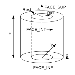
Figure 1.1-a: Géométrie du problème de référence
Il s’agit d’un cylindre de hauteur \(H=\mathrm{20mm}\) , de rayon intérieur \(\mathit{Rint}=\mathrm{4.118mm}\) et de rayon extérieur \(\mathit{Rext}=\mathrm{4.746mm}\) .
1.2. Propriétés de matériaux#
Les propriétés matériaux sont décrites par les paramètres suivants:
Les propriétés matériaux sont décrites par les paramètres suivants:
Propriétés thermiques :
\(\rho {C}_{p}=2000000{\mathit{J.m}}^{-3}.°{C}^{-1}\)
\(\lambda =9999.9{\mathit{W.m}}^{-1}.°{C}^{-1}\)
Propriétés métallurgiques:
\(\mathit{TDEQ}=809°C\)
\(K={\mathrm{1.135.10}}^{-2}\)
\(N=2.187\)
\(\mathit{T1C}=831°C\)
\(\mathit{T2C}=0.°C\)
\({\mathit{QSR}}_{K}=14614\)
\(\mathit{AC}={\mathrm{1.58.10}}^{-4}\)
\(M=4.7\)
\(\mathit{T1R}=949,1°C\)
\(\mathit{T2R}=0.°C\)
\(\mathit{AR}=-5.725\)
\(\mathit{BR}=0.05\)
Propriétés mécaniquesthermo-élastiques:
Module de Young: \(E=80000\mathit{MPa}\)
Coefficient de Poisson: \(\mathit{NU}=0.35\)
Coefficient de dilatation identique pour les phases chaude et froide \({F}_{\mathit{ALPHA}}=8,0\times {10}^{-6}°{C}^{-1}\) et \({C}_{\mathit{ALPHA}}=8,0\times {10}^{-6}°{C}^{-1}\)
Propriétés mécaniques de la loi META_LEMA_ANI
Paramètres liés à la viscosité, phase \(\alpha\) pure
F1_A = 2.39
F1_M = 0.
F1_N = 4.39
F1_Q = 19922.8
Paramètres liés à la viscosité, mélange \(\alpha +\beta\)
F2_A = 0.22
F2_M = 0.77 E-4
F2_N = 2.96
F2_Q = 21023.7
Paramètres liés à la viscosité, phase \(\beta\) pure
C_A = 9.36
C_M = 0.99 E-4
C_N = 6.11
C_Q = 6219
Coefficients de la matrice d’anisotropie dans le plan \((r,\theta ,z)\) , phase a
F_MRR_RR = 0.4414
F_MTT_TT = 0.714
F_MZZ_ZZ = 1
F_MRT_RT = 0.75
F_MRZ_RZ = 0.75
F_MTZ_TZ = 0.75
Coefficients de la matrice d’anisotropie dans le plan \((r,\theta ,z)\) , phase b
C_MRR_RR = 1
C_MTT_TT = 1
C_MZZ_ZZ = 1
C_MRT_RT = 0.75
C_MRZ_RZ = 0.75
C_MTZ_TZ = 0.75
1.3. Conditions aux limites et chargements#
Partie thermique:
On impose une température uniforme sur tout le tube:
Temps (\(s\) ) |
Température (\(°C\) ) |
-1. |
|
36.1 |
|
799.7 |
|
838.67 |
|
876.52 |
|
49.2 |
894.5 |
Partie mécanique:
La partie inférieure du cylindre (\(\text{FACE\_INF}\) ) est bloquée en déplacement suivant \(z\) : \(\mathit{UZ}(x,y,0)=0\)
Toute la partie supérieure du cylindre (\(\text{FACE\_SUP}\) ) a un déplacement suivant \(z\) uniforme
On impose une pression sur la face intérieure du tube (\(\text{FACE\_INT}\) ):
Temps (\(s\) ) |
Pression (\(\mathit{MPa}\) ) |
-1.0 |
|
36.1 |
6.74 |
49.2 |
6.74 |
On tient compte de l’effet de fond sur la partie supérieure du tube (FACE_SUP):
Temps (\(s\) ) |
Pression (\(\mathit{MPa}\) ) |
-1.0 |
|
36.1 |
6.74*coeff |
49.2 |
6.74*coeff |
Avec \(\mathit{coef}=(\mathit{Rint}\times \mathit{Rint})/[(\mathit{Rext}\times \mathit{Rext})-(\mathit{Rint}\times \mathit{Rint})]\)