RBE3 on isolated node

Dear all, I’m quite new to code-aster and in I’m working with Salome Meca 9.13, Code Aster 17.4 on Windows11.

I’m trying to understand the right procedure to apply a BC on a node connected to che main mesh with a RBE3 element.

Something like below image:

[upl-image-preview uuid=a9a89735-59f2-49b1-a37d-d39a1e39a1e4 url=

alt={TEXT?}]
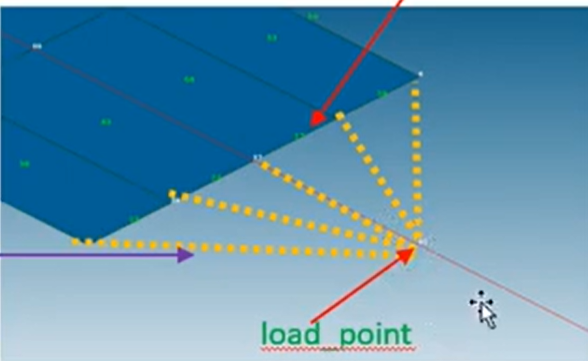
Which component shoud I create on Mesh (or geometry) and which one on AsterStudy

By now I was creating a 3D beam on geometry, with groups of 3D, Fix Face and RBE3 face (Load Face).

Then in mesh I get groups from geometry and create an additional node in front of RBE3 face 10mm away, with his group and 0D element on it (Load_Point and 0D_Load).

Ottengo un errore di singolarità della mesh

mesh = LIRE_MAILLAGE(FORMAT=‘MED’,

                 UNITE=20)

model = AFFE_MODELE(AFFE=(_F(GROUP_MA=(‘Load_Face’, ‘Fix_Face’, ‘Beam’),

                         MODELISATION='3D',

                         PHENOMENE='MECANIQUE'),

                      _F(GROUP_MA=('0D_Load', ),

                         MODELISATION='DIS_TR',

                         PHENOMENE='MECANIQUE')),

                MAILLAGE=mesh)

elemprop = AFFE_CARA_ELEM(DISCRET=_F(CARA=‘K_TR_D_N’,

                                 GROUP_MA=('0D_Load', ),

                                 REPERE='GLOBAL',

                                 VALE=(1000000000.0, 1000000000.0, 1000000000.0, 1000000000.0, 1000000000.0, 1000000000.0)),

                      MODELE=model)

steel = DEFI_MATERIAU(ELAS=_F(E=210000.0,

                          NU=0.3))

fieldmat = AFFE_MATERIAU(AFFE=_F(MATER=(steel, ),

                             TOUT='OUI'),

                     MAILLAGE=mesh)

load = AFFE_CHAR_MECA(DDL_IMPO=_F(DX=0.0,

                              DY=0.0,

                              DZ=0.0,

                              GROUP_NO=('Fix_Face', )),

                  FORCE_NODALE=_F(FX=1000.0,

                                  GROUP_NO=('Load_Point', )),

                  LIAISON_RBE3=_F(COEF_ESCL=(1.0, ),

                                  DDL_ESCL=('DX-DY-DZ' ),

                                  DDL_MAIT=('DX', 'DY', 'DZ'),

                                  GROUP_NO_ESCL=('Load_Face', ),

                                  GROUP_NO_MAIT=('Load_Point', )),

                  MODELE=model)

reslin = MECA_STATIQUE(CARA_ELEM=elemprop,

                   CHAM_MATER=fieldmat,

                   MODELE=model,

                   OPTION='SIEF_ELGA')

reslin = CALC_CHAMP(reuse=reslin,

                CONTRAINTE=('SIGM_NOEU', ),

                FORCE=('REAC_NODA', ),

                RESULTAT=reslin)

IMPR_RESU(FORMAT=‘MED’,

      RESU=_F(MAILLAGE=mesh,

              NOM_CHAM=('SIGM_NOEU', 'DEPL', 'REAC_NODA'),

              RESULTAT=reslin),

      UNITE=80)

@mastraa

before discussing the way to handle an RBE3 i see in your .comm file

reslin = MECA_STATIQUE(CARA_ELEM=elemprop,
CHAM_MATER=fieldmat,
MODELE=model,
OPTION='SIEF_ELGA')

for it to work there should be at least a section like this

EXCIT=(
	 _F(CHARGE=load,),
),

and it is a very bad idea to mix up in a single AFFE_CHAR_MECA

DDL_IMPO that is boundary condition

FORCE_NODALE or all loads

LIAISON_RBE3 or any internal links of this type

use 3 AFFE_CHAR_MECA in your case

then with

VALE=(1000000000.0, 1000000000.0, 1000000000.0, 1000000000.0, 1000000000.0, 1000000000.0)),

with such a high stiffness on the point element whatever the units are i doubt it will allow physical meaningful displacement

Ok, after several attempts where I surely made mistake with coupling DIS_T/TR with K_T_D_N…I finally prepared the right RBE definition and made a newbie mistake…

Thank you, the EXCIT was the issue this time.

About other suggestion you’re right, not the best way and I will improve the comm. Anyway it works.

Thank you!

Regarding stifness I found out something I cannot explain.

I follow your suggestion to reduce 0D element stiffness.

With 210.000.000 Total reaction on Fix face i 10N

reducing to 210.000 (same as my material): 5000N

21.000: 9000N

1.0: 9999N

0.1 or 0.0: 10000N

Why this happens?

In any case stress component on X direction is 100MPa (=F/A=10000/(10*10))

Here my estraction operation

reac = POST_RELEVE_T(

ACTION=_F(

GROUP_NO=('Fix_Face', ), 

INTITULE='REACTION', 

NOM_CHAM='REAC_NODA', 

OPERATION=('EXTRACTION', ), 

RESULTANTE=('DX', ), 

RESULTAT=reslin

)

)

EDIT: It was not a newbie mistake. I figured out that if you try to modify MECA_STATIQUE field in AsterStudy sometimes (or always I can’t say) it remove EXCIT option from the definition.

Probably in these days I already tested the right .comm file but while I was updating MECA_STATIQUE it removes EXCIT and the errors came from that. Be careful.

It happens once more with a file that works before so I check on MECA_STATIQUE (the only updated sentence) and figured out.

@mastraa

[quote

I follow your suggestion to reduce 0D element stiffness.

With 210.000.000 Total reaction on Fix face i 10N

reducing to 210.000 (same as my material): 5000N

21.000: 9000N

1.0: 9999N

0.1 or 0.0: 10000N

[/quote]

try to be clearer

i do not understand what you mean

i the case depicted by the picture the right value for the stiffness in the load direction is obviously null or almost null

Ok, at the end of my experiment I figured out the same. K should be null.

I don’t grasp the the theory behind…

I mean: I thought the stiffness was the the stiffness of ideal beam/spring connecting nodes of 0D to face ones.

With my ‘experiment’ I got correct stress along force direction for every stiffness set.

But fixed face reaction results in 10.000N (as expected) only when stiffness was around 0. And I can’t understand why

@mastraa

it is just basic theory of elasticity elasticity

a VALE of 1000000000.0 for a translation DOF on a OD element means that a force of 1000000000.0=1E9 unit of force will move the point 1 unit of length

then the stress will be calculated from these displacements

@jeanpierreaubry

Thank you, now I understand what this stiffness means!

I thought it was stiffness of 0D to structure connection, not 0D to the ground.

Ansys permuta to define it rigid, deformable or ‘beam’ so I thought it was like this ‘beam’…

Now it’s clear, very thank you